Fan controlled by Raspberry Pi
After installing a new window in my basement, humidity in the room became pretty high, there was a musty smell, and I even got some patches of mold on the outside walls. My first attempt of airing the room on a regular basis proofed to be quite cumbersome and not overly effective. Especially in the summer time the only good time to air the room is in the early morning hours, when I am usually still in bed. When I started googling for a solution to this problem, I stumbled upon devices that measure the humidity and temperature inside and outside and will activate a fan when the conditions are good, that is the dew point outside is lower than the dew point inside. The price of these devices was somewhere between 500€ and 600€, not including the fans. That was when I though I might try to build this kind of device on my own based on a Raspberry Pi.The fan control device
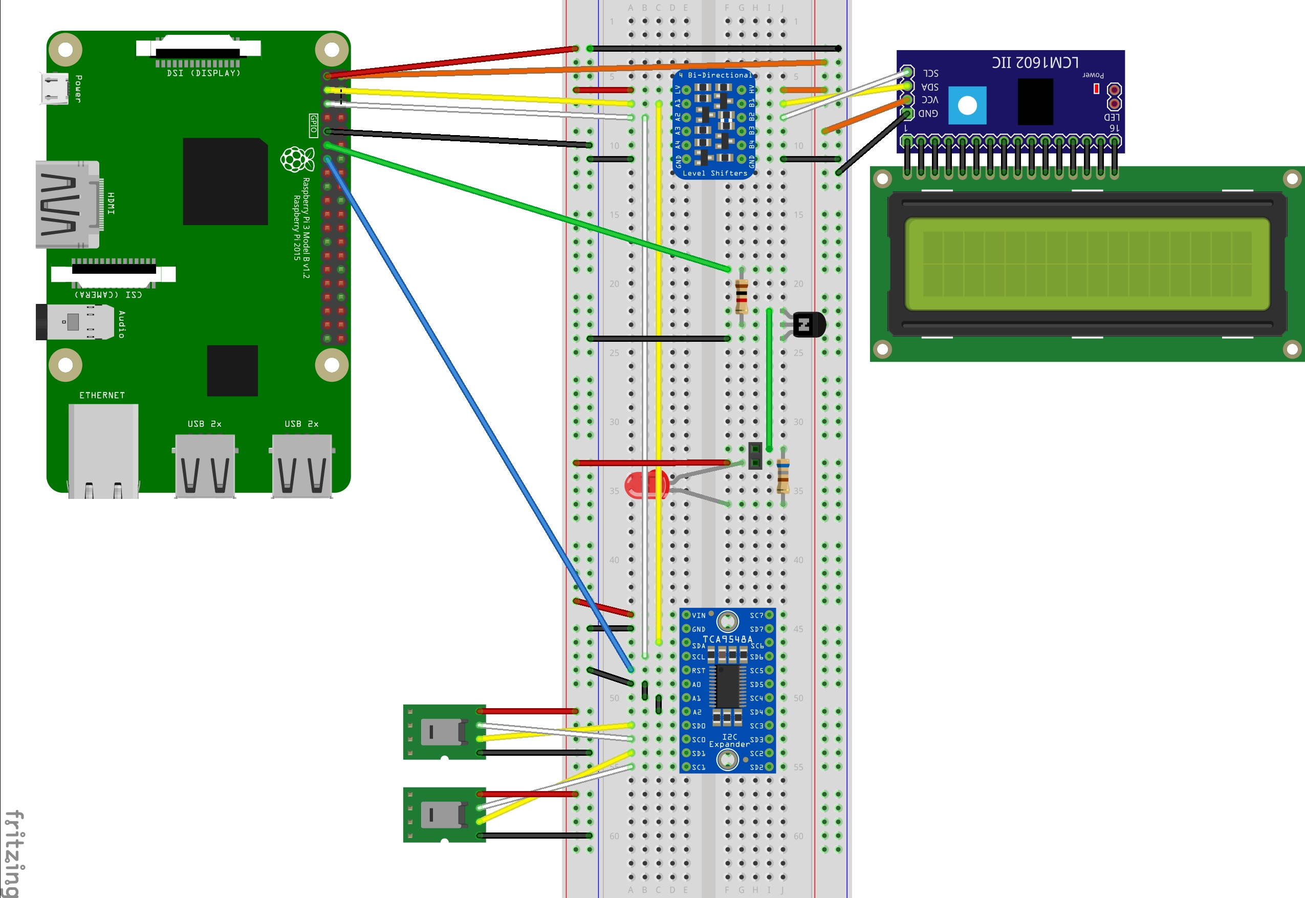
This is my shopping list I used to implement the device:
- Raspberry Pi 3b
- SunFounder I2C serial 20x4 LCD display
- 4 channel bidirectional logic level converter
- Two temperature / humidity sensors with housing AM2315
- 8 channel TCA9548A I2C multiplexer breakout board
- Antrax SB1100 SwitchBox-Relais
- NPN transistor and some resistors
- LED
- solid housing to protect the Raspi from the environment
How it all fits together
Sensors
Of course the most essential devices are the two temperature / humidity sensors. These sensors can be connected to the I2C bus of the Raspberry Pi. Unfortunately, these sensors have a fixed ID, and hence, it is impossible to have two of these sensors on the bus at the same time. That's why we need the multiplexer.Multiplexer
The multiplexer connects the I2C bus of the Raspberry Pi to one of eight different I2c busses. We only need two of them for our two sensors. Before a sensor can be read, we have to tell the multiplexer which of the connected I2C devices we want to activate. The multiplexer has a reset function, that I always use before switching to a new device. I made some tests without resetting the multiplexer first, and didn't have any problems. Nevertheless, I thought it could be better for long term stability to use the reset function. There has to be a reason that the multiplexer has this function, and it sure won't hurt using it.Display
Because I wanted to see what my device is / was doing without having to use my computer, I added the display. The display shows the temperature, the humidity and the dew point in my basement as well as outside. Furthermore, it shows whether the fan is currently active and how long it was active today.Logic level converter
The logic level converter is needed because the display uses 5V, but the Raspberry Pi works on a 3,3V level. There seem to be people that were able to operate the display without the converter, but I prefer to stay in the specified range of my components. Anyway, that thing is very cheap, so why not use it and be on the safe side.Switch box
The switch box is the device that controls the actual fans operated at 220V. Since I didn't want to have the high voltage in my housing, it was the best option I found. A cheaper alternative would have been to use one of those relay cards, but this would have involved high voltage in my box. Another cheaper option would have been using sockets that can be controlled by a remote control (or a corresponding Raspberry module), but the problem with these is, that you will have no way of knowing whether the signal you sent was lost, or whether it did turn the socket on / off as intended. Especially devices that only have a single on/off button would need a feedback channel to let the Raspberry know whether they are active or not. Otherwise, you might end up turning the fan on when it is supposed to be turned off and vice versa, because one "click" was lost.LED
The LED is not really necessary, but I found it very useful while I was testing my setup. The LED will be turned on and off along with the fan, so I was able to test my software without having the switch box connected.NPN transistor
Instead of connecting the switch box (and the LED) directly to the GPIO pin, a NPN transistor and a few resistors were used to prevent that the pin draws too much current. According to what I have found the maximal current per pin is 16mA, which probably would have been exceeded with the current setup.This is the circuit I set up
The fan
For the fan I used a comparably cheap one with a recuperator (Awenta HRV 100) that changes its flow direction every minute to prevent loosing too much thermal energy. After I found out that the fan didn't lock the channel, I added an additional shutter (Maico AE 10). This was because there was quite a lot of air flowing through the channel even when the fan was inactive.The software
Functions
To avoid problems like memory leaks, file handle leaks etc., I decided against a software that is running the whole time. Instead the whole software was set up to be run repeatedly once a minute (started by a cron job).The software basically performs the following tasks:
- Load the status (control parameters)
- Measure the temperature / humidity
- Compute the dew point
- Decide whether to turn the fan on or not (based on the status and the measured values)
- Log the current status
- Update the daily temperature / humidity chart
- Save the status
- Send the daily chart by mail
Programming language
Because I am not very familiar with Python, I thought that I would be better off using Java for the entire project. Even though most of the sample code I found on the net is written in Python, I thought that it would pay off to migrate everything into Java, because I would be a lot faster with the glue (the actual control logic and the report generation) between the driver code snippets. Most of the components could be controlled by sending / receiving just a few bytes. The most complicated part by far was getting the display to work, because it uses a rather complicated protocol. However, with a working Python sample at hand, it was still pretty easy to make sure that the exact same bytes were sent.Testing the software
Because testing the software with the actual hardware would be rather complicated and slow, I decided to start with a test-driven design. All hardware components were accessed via interfaces, and I created a series of dummy hardware components that could be used in the tests (e.g. sensors returning random temperatures etc.). This allowed me to quickly test the complete system easily using automated tests based on junit. Of course the actual hardware had to be tested manually.Charts
Especially in the beginning, I wanted to have a close look at what the software was doing, and how it affected the humidity in the room. The logs that were produced by the software proved to be hard to analyse because of the large amount of data. That's why I implemented a chart generator to visualize the measured values. Currently I am still toying around with various parameters to control the fans (e.g. minimal time of activity, minimal time of inactivity etc.). Maybe I will add a web-frontend to the system to allow changing the parameters. Currently, this still has to be done by editing XML files on the system.

And here are some impressions of what it looked like in the end

